Marko Buha
Software Engineering Master's student with an array of experiences in embedded software development
Software Engineering Master's student with an array of experiences in embedded software development
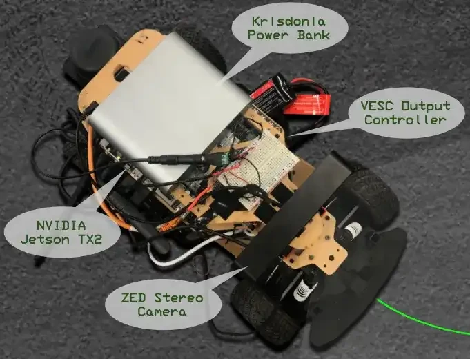
Capstone project to demonstrate an autonomous parking system on a 1/10th scale car
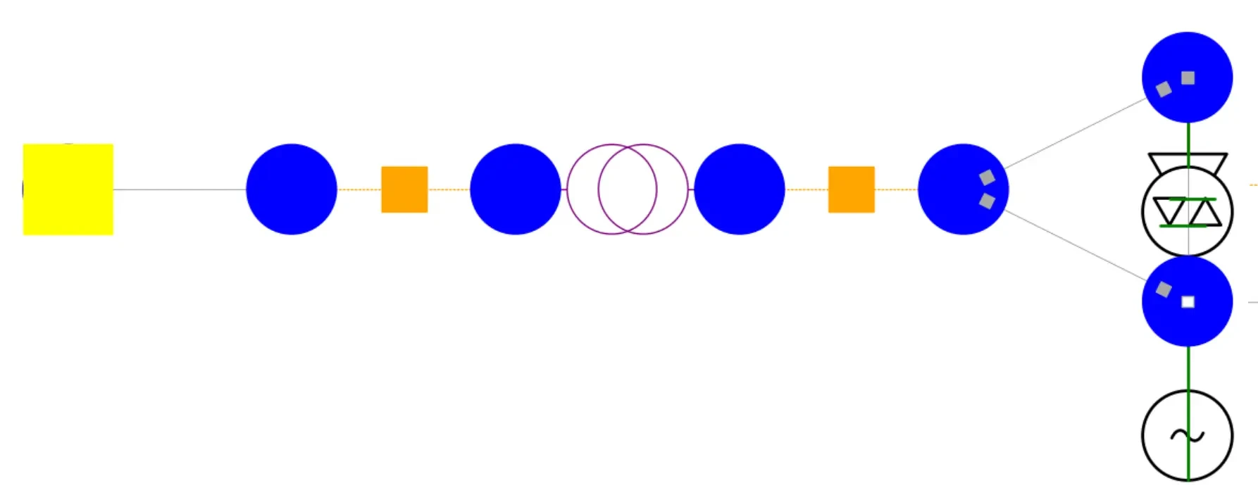
Developed a power system simulation package
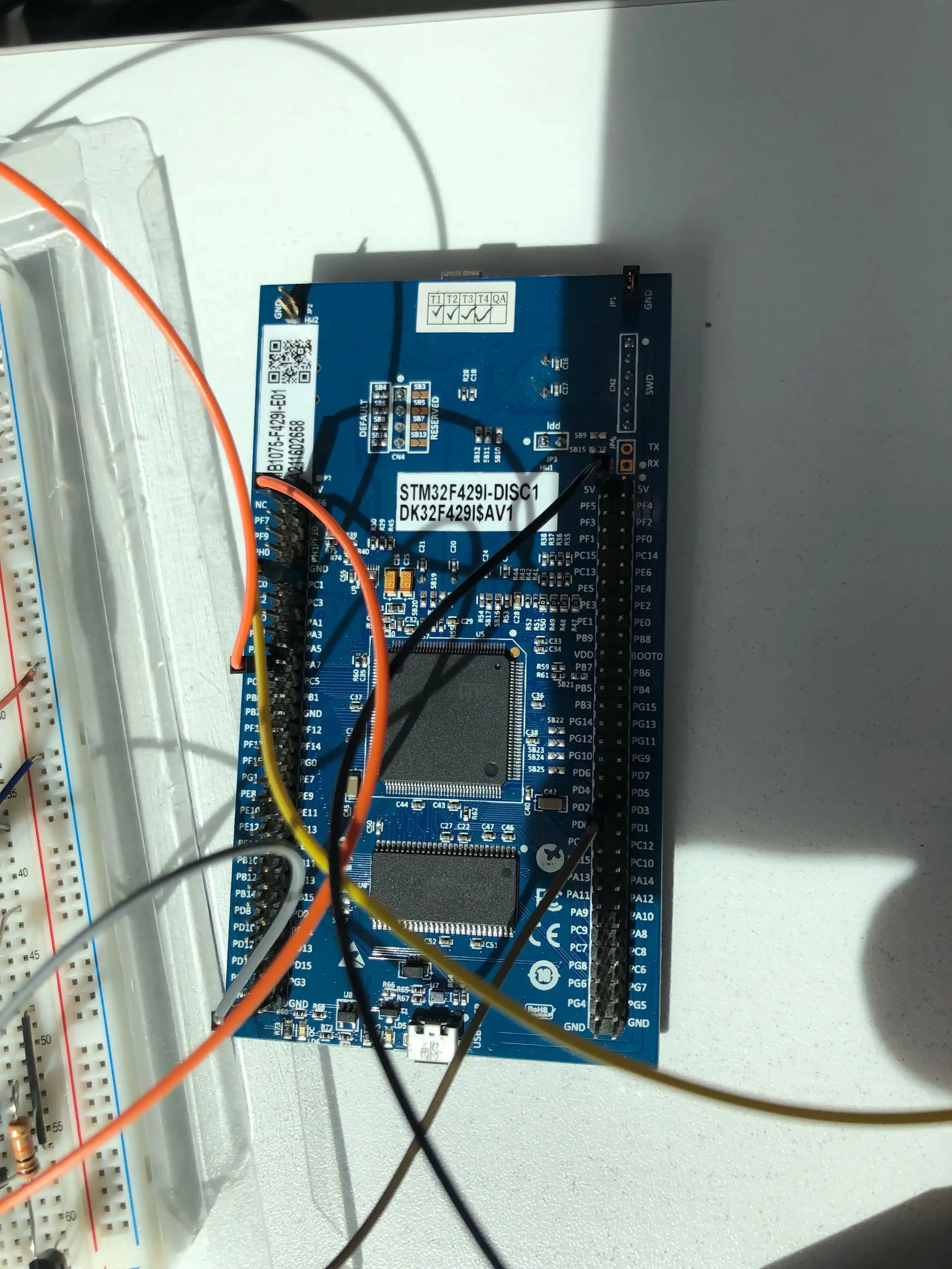
Controller to adjust fan's speed in response to temperature changes
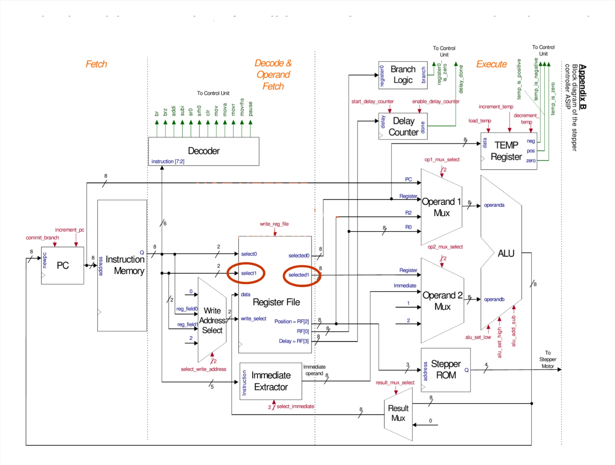
ASIP in Verilog to control stepper motor
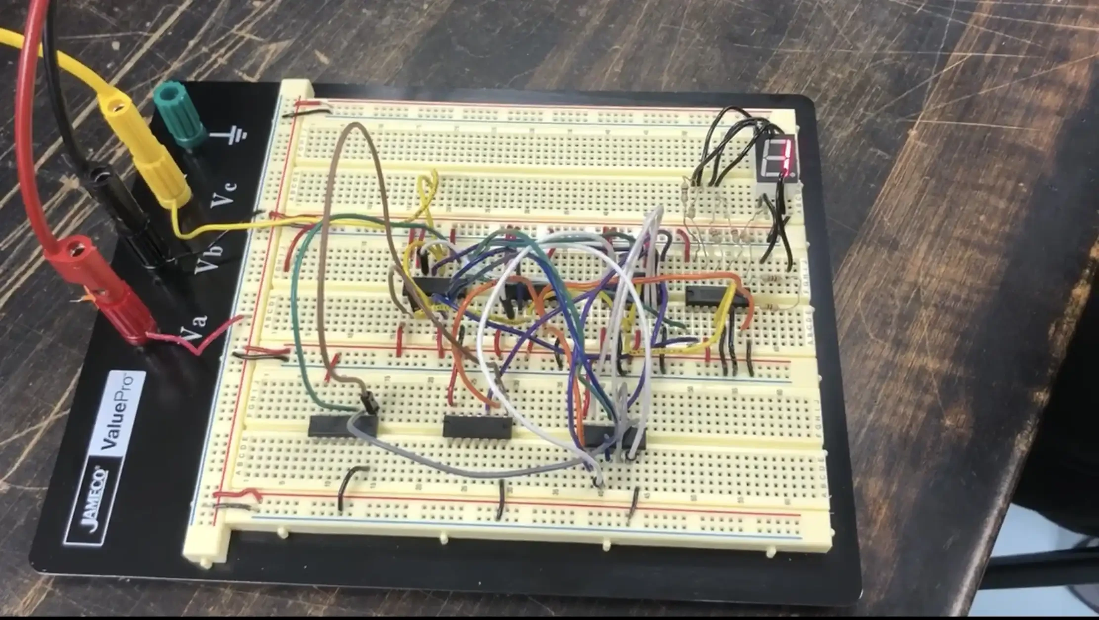
Circuitry to cycle through different states
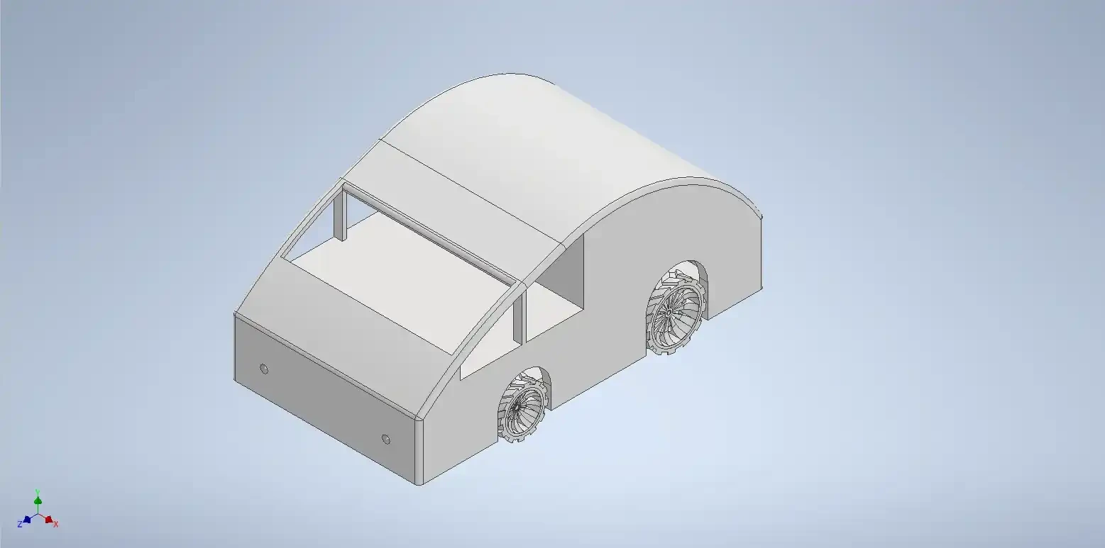
Remote controlled car CADed in Autodesk Inventor for a class final project
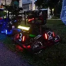
Robotics team
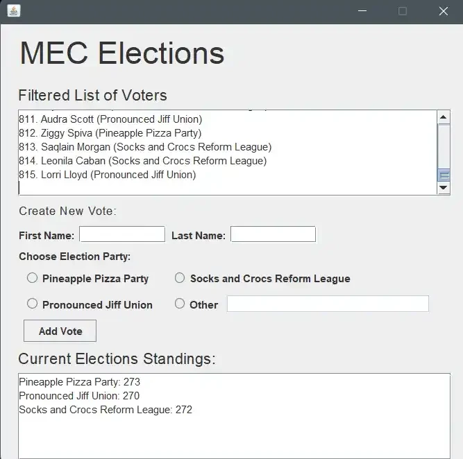
Platform to run elections
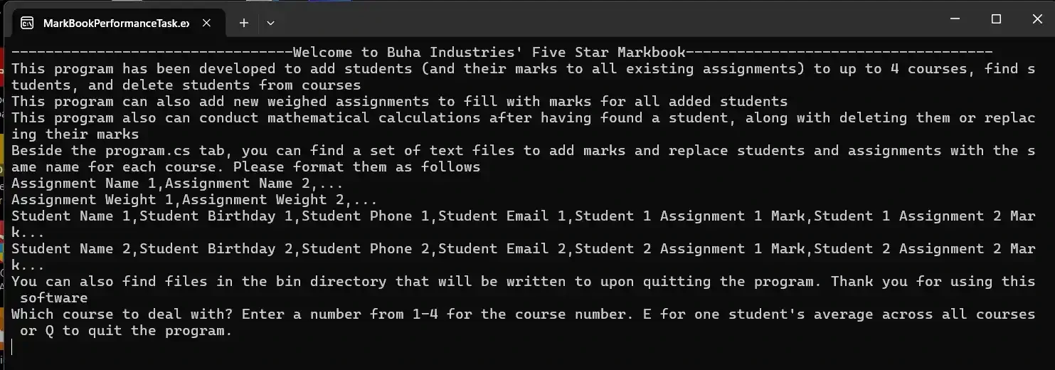
System to store grades for a teacher's classes
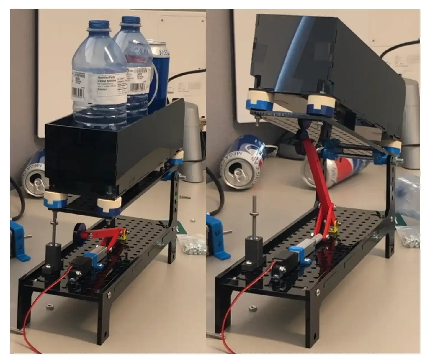
Mechanism to dispense a hopper in a recycling plant


